• Hello there guest and Welcome to The #1 Classic Mustang forum!
    To gain full access you must Register. Registration is free and it takes only a few moments to complete.
    Already a member? Login here then!

Meet Crusty Tank

cmayna

DILLIGARA?
Donator
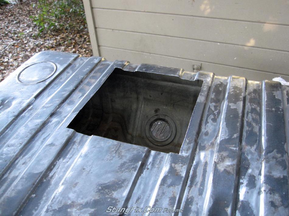
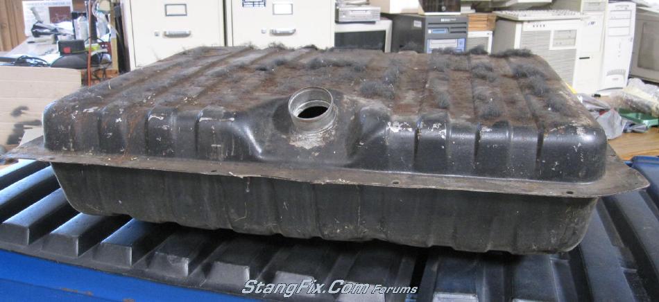
Well here's my newly acquired crusty old 22 gallon tank which I'll be using for sending unit testing. It was free so I jumped on it during lunch. Gonna clean up the outside a little and chop a hole in the top as Sam suggested.

All I'm most concerned is the accuracy for 1/4 and 1/2 tank levels. Don't really care about how accurate it reads when I just filled the tank.

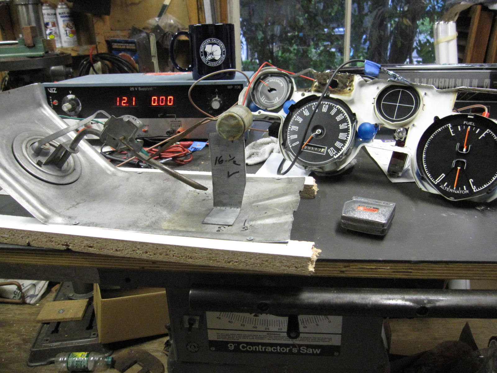
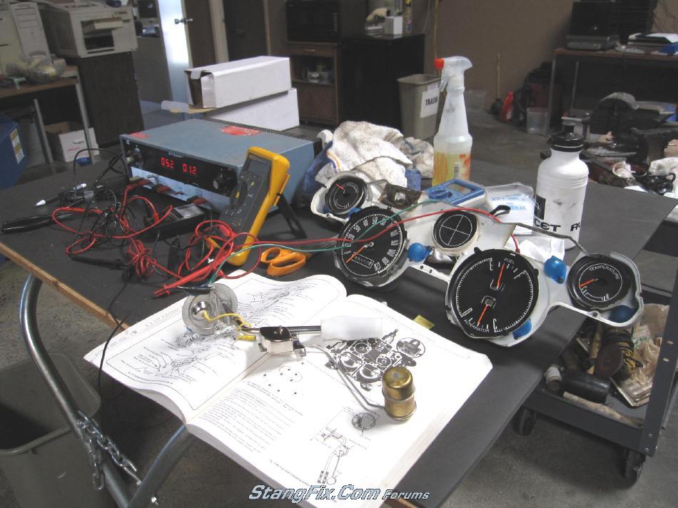
Lot more fixture set up to do, with gauges, dc power supply, etc. Last night I did test the reading of a 65-68 and a 69 sending unit. Also powered up Shag's old stock fuel gauge with a variable DC power supply and it worked. Going to try Red's original gauge tonight.


4_30_09_10_1_40_56.JPG


4_30_09_10_1_56_16.JPG
 
Last edited by a moderator:
You want a job with Midlife Harness Restorations? You look well set-up for electrical work!
 
Frank,
I didn't blow up when I cut the opening on top.


4_30_09_10_6_01_36.JPG
 
Last edited by a moderator:
Right on, Craig, very cool.

I'll pick mine up from Dave here in a couple weeks and then get moving.

I just had all my gauges calibrated so I know the fuel gauge is good.
 
This weekend, I'll be testing tweaking a 65-68 as well as a 69 repro sending unit using both Red and Shag's gauges which per my test last night are reading identically. Will post findings and pics.

Until I get my hands on some 170 and 180 ohm resistors, I'll hold from touching Red and Shag's Autometer gauges/sending units. I do though have a 69 OEM sending unit on it's way to me and if it works, I might try installing it into Shag without adding a resistor which per Autometer's website's is the way to go.
 
Damn, looks like Frankenstein's lab!

Wow, way more detail than I am willing to do!

My 67 seems accurate still with the Autometer phantom gauges and the 65 is pretty accurate as well.

Good luck...

Mel
 
Fry's or a Marva Dow electronics can get you the resistor values you need. You might want to get a 1k ohm potentiometer vice a specific resistor so you can see how variable the levels are due to resistance fluctuations...

Nice little project!
 
Craig,
I'm just now getting to this on my car. I have the free tank I got from Dave cut open much like yours pictured above.

I don't have all the fancy electrical stuff up there, so I'm still trying to figure out exactly how I want to rig this up.

So far I measured the resistance of my sender and have about 8 ohms full and 79 ohms empty. I have the sender in the tank with 4 gallons of water. First off, I was surprised that it took about 1.5 gal of water to get to the pickup tube. I measured the resistance with the float on 4 gal and I'm around 50 ohms.

Is there a linear relationship between the resistance on the sender and what the gauge shows? If so, I should be able to set 1/4 tank on the gauge at 61 ohms on the sender, and 1/2 tank at 43 ohms.

There is a little peak on the sender arm just before the float. I plan on using that for my measurements, ie, with 4 gal in the tank, the peak would sit on about a 3 3/8" prop. Not sure on what to use on the prop yet, but was thinking I could just cut what I removed from the top of the tank into strips, and bend them to length and trim to fit exactly under the peak on the arm. Then repeat with 5 gal, 8 gal, and 10 gal so I have benchmarks for the 16 and 20 gal tanks at 1/4 and 1/2.

Does all that sound about right?
 
Sam,
I believe I have done a couple posts about this bracket I made to adjust sending units (see below pic).

With the above tank that I chopped the sunroof in, I first installed a sending unit then put in 4 gallons to represent a quarter tank for a 16 gallon. Measured from the bottom of the tank to the centerline of the float. Took that measurement and made a 4 gallon spacer which is original measurement less half of the float diameter to equal a distance from bottom of tank to bottom of float.

Now with your sending unit attached to the below bracket, all you do is (assuming you are running a 16 gallon tank) attach your gauge's sending unit wire (via a long extension wire enough to go to the driver's seat area) to the sending unit, ground the bracket or sending unit somewhere nearby, place the 4 gallon spacer under the float. Turn your key on and watch the needle. If it reads a tad low, you bend the float down which is straightening the float's arm. Or looking at the below pic, you would be straightening the float's arm. Pretend "c" is your elbow. Grab "C" with a pair of needle nose pliers and arm "B" with another set of pliers (near C) and straighten "B" just a tad.

Put the 4 gallon spacer back under the float and turn the key back on. Keep tweaking until you like it.

I did not devise anything based upon the number of ohms at 1/4, 1/2, etc.

sendingunit.JPG
 
Last edited by a moderator:
I am also watching this thread with great interest. :wor

But I do have some questions. It looks as if you have a brand new sending unit. I bought a replacement one a few years back and it was a cheap one, so I need to replace it. The gas gauge in my 67 coupe was right on, I my have tweaked at one point, but it was perfect. Then I let it sit for 10 years with a full tank of gas. :char Needless to say the tank was thrown away and I found a replacement from a vmf'er.

I need to adjust the sending unit on Dad's vert again this weekend. Those ohm readings sound like what I was getting when I played with it the first time. The problem with the sending unit in the vert is it that it is 1/4 off. That is 3/4 means full and 1/4 means 1/2 a tank. When I pull it out this time I need to bend (adjust) the float rod. My plan is to see where it sits now at 1/4 and get an ohm reading, then at 1/2 and get an ohm reading. Then bend the rod so that 1/4 reading location is now the 1/2 spot.

I worked on it about a month ago, or a tank of gas ago. I had just replaced the rubber "O" ring. I was not planning on replacing it again, or do you put a new one on every time?

Just a little Vaseline kept the "O" ring in place. :thu

fd
 
The ohms thing is right out. Don't bother. Resistance on the sender is irrelevant, the resistance into the gauge matters. So splitting the difference on the sender doesn't do anything to make the gauge read half.

So I set up my contraption just like Craig did, and that worked...somewhat. Let me clarify, the technique is sound, my sender is crap. I was able to get it to read right on at 1/4 and at 1/2, but not both. I ended up going with 1/4 being correct, 1/2 tank reads closer to 3/4 on the gauge.

I saw recently that NPD has a higher end sender available, I'm going to try that and see what it does. For now though, at least I know when I am getting low and need to find a place to stop.
 
Keep us posted on the progress Craig. I'm especially interested in the 16 gal tank calibrations. I'll be working on an in tank high pressure fuel pump set up for an EFI motor that can be installed in a completely stock tank. It is very do-able, but one of the mods needed is to install the float and resistor on the modified assembly. Methods to ensure proper cal would be very useful!
 
So what is the main objective of this science project?

So you can install a larger tank and use the same sending unit and gauge?
 
Same gauge but as you go from 16 to 20 to 22, the sending unit's float arm becomes longer.
 
Here's a pic of a sending unit in the fixture with a 16 gallon 1/2 tank spacer under the float. Note the gauge reading.

FuelSendingUnitb.JPG
 
Last edited by a moderator:
Back
Top