• Hello there guest and Welcome to The #1 Classic Mustang forum!
    To gain full access you must Register. Registration is free and it takes only a few moments to complete.
    Already a member? Login here then!

30 Amp Relay wiring help

68EFIvert

Well-Known Member
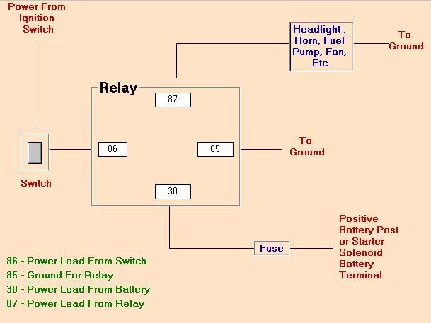
I am about to wire up my new Meziere Electric water pump and I would like to run this through a relay. I don't want to spend the $30 tey are asking for a relay kit and would rather use one I already own. Does anyone know how to hook up a relay? The pump has two wires, a ground a power. The power has a fuse built in. Thanks!!!!
 
There are 5 terminals on an automotive relay and only 4 of them usually get connected. They have a standard numbering system that goes a little like this:

#85 & #86 run through the coil in the relay (one connected to ground, one to "signal", doesn't matter which)
#87a is the resting positon (usually not connected to anything)
#30 is what gets contacted when the relay energizes (connected to +12V)
#87 is what contacts #30 when the relay energizes (it is the output)

That's probably a crappy explanation so I'll apologize in advance for the confusion.
 
Well, I followed it and understood it.

Basically, a relay is an electronic version of a toggle switch. Two lines (ground and the relay activation line) signals whether the toggle is ON or OFF. The basic toggle switch changes from one output to another. In the OFF position, the output is typically a default signal (the unused line discussed above). Normally, the toggle switch in the OFF position would take whatever signal is on this line and put it on the output line. In your case, the default signal is nothing, so you don't connect anything to that input line. In the ON position, you want the full 12V to go to the output signal, so you hook up the 12V to that input line.

Now then...the amount of current flow depends upon your latitude above or below the equator. For folks who live south of the equator, the current flow is counterclockwise, so you have to orient the relay such that your output signal is to the left of the input signal. Reverse directions if you live above the equator. God help those who live ON the equator or have to cross it every day to go to work. In that case, one has to invoke the Higgs Bosun...
 
Thanks for the help! I am glad I don't live on the equator. I have a hard enough time understanding electronics. I don't know what I would do if everything I know to be correct is really backwards. :craz
 
I need some help! I must be doing something simple wrong. I have wired two relays this way and neither is working. I am getting power from the battery and on the other side of the 30 amp fuse. I know the fans work since I ran a direct wire from the battery to them and they came on. I am grounding the signal wire and it is not doing anything. This is how I wired it.

30 to battery with inline 30 amp fuse
87 to + side of fans
85 to sending unit (signal)
86 to ground
87a is taped off and not connected.

It doesn't matter the order of 85/86 does it? Could both relays be bad? I pulled a relay (plug in part) from another accessory I have that works and it did not do a thing.
 
just out of meaness you might try switching your ground & signal wires on the relay. try the 85 as ground & make sure your ground connections to the body are good.


Relay Wiring Diagram

A relay is typically used to control a component that draws high amperage. The relay allows full power to the component without needing a switch that can carry the amps. The switch only controls the relay. The relay then provides a direct connection to the battery. It should be noted that either the power(86) or ground(85) in the relay control circuit can be switched. In the case of a horn, the horn button would be used to switch the ground lead(85) and power(86) would be provided directly from the fuse box.

This is a typical wiring diagram for a standard relay installed for
headlights, horn, fuel pump, electric fan, etc. If the relay has a
5th terminal, it is not used.

relaywire.jpg
 
Well I got it to work by moving the Ground (86) to the I post on the solenoid. The 85 is still hooked to the sending unit. I don't have a wire that actually connects to a ground on the car. :scar The only grounds I have in the setup are where the fans ground. Is this wrong? It comes on when I ground the sending unit to the car. I suppose that completes the circuit and the reason it should come on when the sending unit reaches the appropriate temp.

Thanks for the diagram.
 
Wouldn't the ground on your diagram be 85 (sending unit on my wiring)? It seems like the ground is made when the sending unit is triggered by the water reaching a certain temp. If not what wire would go to the sending unit?

Thanks for the help!
 
i'll make a note & look at a diagram i have in the shop for a relay hookup using a temp switch. most of the time i use an adjustable switch to trigger the relay & fan & it may hook up a little different.
 
See below. The first is the way you want to do it, the other is if you also want it hooked up to a toggle switch. I included both in case someone searching this thread may want to go the other route. The last is if someone doesn't want a relay installed. HTH!

_relay_diagram.jpg


_relay_diagram_w_switch.jpg


And without a relay:

_no_relay_diagram.jpg
 
Back
Top